Trailer Brake Control Wiring Diagram : Curt Brake Controller Wiring Diagram Collection : Our team of professionals is here to help you learn how to locate the problem and understand how to perform different tests.
Dapatkan link
Facebook
X
Pinterest
Email
Aplikasi Lainnya
Trailer Brake Control Wiring Diagram : Curt Brake Controller Wiring Diagram Collection : Our team of professionals is here to help you learn how to locate the problem and understand how to perform different tests.. A number of standards prevail in north america, or parts of it, for trailer connectors, the electrical connectors between vehicles and the trailers they tow that provide a means of control for the trailers. This harness can be installed by following the generic wiring guide. I don't have a wiring diagram on me, so i don't know which. Brake pressure brake fluid trac ctrl check trans trailer abs washer fluid (left turn) air bag water in fuel coolant level check elect sys park cruise abs (right turn) wait to start. Using a trailer is quickly becoming part of the american this brake control installation was performed on a nissan titan pickup, but your application will be similar.
Each component ought to be set and connected with other parts in specific way. Using a trailer is quickly becoming part of the american this brake control installation was performed on a nissan titan pickup, but your application will be similar. Use pigtail wiring harness included. Photo by adam wright 2010. Hi everyone, i just got a tekonsha voyager trailer brake controller.
Wiring Diagram For A Trailer Brake Controller | Trailer ... from trailer-wiring-diagram.com Time basedintuitive, vertical manual slide matches the way a. (see diagram for mounting the p3). It's crucial to diagnose a trailer wiring problem early. And i got the tekonsha p3: • verify that the trailer brake controller is powering on. Not sure which wires attach to what on your trailer connectors? Let's see what types of connectors the trailer light wiring industry uses today. This harness can be installed by following the generic wiring guide.
All our tow pro brake controller wiring guides are online, so make sure you have a good look before setting off.
Otherwise, the arrangement won't work… I wired up an extra third brake light to the brown pin, but of course it also blinks when i. What color wire is what with the remaining 3 wires? All our tow pro brake controller wiring guides are online, so make sure you have a good look before setting off. Good unit and available most anywhere. • verify that the trailer brake controller is powering on. On the 4 wire plug i know the brown wire is ground. Wiring diagram for stock trailer refrence lovely trailer wiring. The trailer brake control (tbc) module varies the pwm signal based on various inputs such as the brake torque message, the manual slider switch and the gain buttons. This harness can be installed by following the generic wiring guide. Time basedintuitive, vertical manual slide matches the way a. Brake controller installation on a full size ford truck or suv. A number of standards prevail in north america, or parts of it, for trailer connectors, the electrical connectors between vehicles and the trailers they tow that provide a means of control for the trailers.
Brake controller wiring & brackets. The trailer wiring diagrams listed below, should help identify any wiring issues you may have with your trailer. Need a trailer wiring diagram? Brake controller installation on a full size ford truck or suv. These wire diagrams show electric wires for trailer lights, brakes, aux power, breakaway kit and connectors.
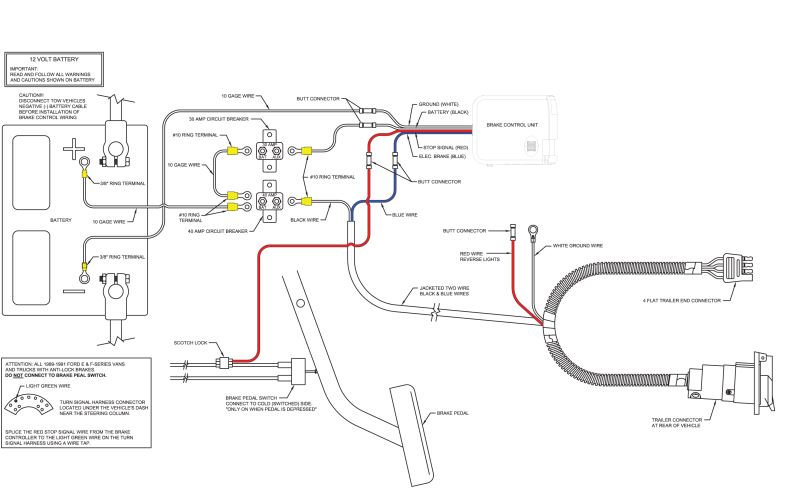
Curt Universal Installation Kit for Trailer Brake ... from www.etrailer.com Typical vehicle brake control wiring diagram. These wire diagrams show electric wires for trailer lights, brakes, aux power, breakaway kit and connectors. Refer to wiring diagram set 95, trailer/camper adapter for schematic and connector information. This brake controller wiring diagram shows which wire goes where. On the 4 wire plug i know the brown wire is ground. Hi everyone, i just got a tekonsha voyager trailer brake controller. Just follow the hookup diagram in the mercedes service letter. This connector allows you two options to wire your brake control.
This harness can be installed by following the generic wiring guide.
Wiring diagram for stock trailer refrence lovely trailer wiring. There seems to be a cable harness. Photo by adam wright 2010. This brake controller wiring diagram shows which wire goes where. Time basedintuitive, vertical manual slide matches the way a. Run dedicated power lines to both the 7way 12v pin and the brake controller (both its 12v feed and output to the 7way connector) with either a 30a fuse or a 30a circuit breaker. Otherwise, the arrangement won't work… Typical vehicle brake control wiring diagram. There is supposed to be a short 4 wire harness that you can buy the plugs in to the factory one but i cannot find the part number. It came with a ford harness, which i plugged into the or do i have what i need already and just missed it in the back? How brake light wiring works. The trailer wiring diagrams listed below, should help identify any wiring issues you may have with your trailer. I wired up an extra third brake light to the brown pin, but of course it also blinks when i.
This brake controller wiring diagram shows which wire goes where. How brake light wiring works. And i got the tekonsha p3: Do you know if the brake controller output pin has any output on our trucks if there's no brake controller installed? I wired up an extra third brake light to the brown pin, but of course it also blinks when i.
Ford Trailer Brake Controller Wiring Diagram | Free Wiring ... from ricardolevinsmorales.com And i got the tekonsha p3: All our tow pro brake controller wiring guides are online, so make sure you have a good look before setting off. Our trailer wiring diagram is a colour coded guide designed to help you wire your trailer plug or socket. How much voltage should a trailer brake controller put out? I wired up an extra third brake light to the brown pin, but of course it also blinks when i. Trailer plug wiring is standardized across all vehicles, no point trying to find vehicle specific info. The part features an led indicator that shows power setting and. Each component ought to be set and connected with other parts in specific way.
And i got the tekonsha p3:
A brake controller has only one output wire. Time basedintuitive, vertical manual slide matches the way a. Brake controller wiring & brackets. Just follow the hookup diagram in the mercedes service letter. All our tow pro brake controller wiring guides are online, so make sure you have a good look before setting off. Let's see what types of connectors the trailer light wiring industry uses today. Wiring diagram for stock trailer refrence lovely trailer wiring. Run dedicated power lines to both the 7way 12v pin and the brake controller (both its 12v feed and output to the 7way connector) with either a 30a fuse or a 30a circuit breaker. The following trailer wiring diagram(s) and explanations are a cross between an electrical schematic and wiring on a trailer. Good wiring diagrams for body builders and troubleshooting. Need a wiring diagram for the trailer hitch for same car. The trailer wiring diagrams listed below, should help identify any wiring issues you may have with your trailer. It came with a ford harness, which i plugged into the or do i have what i need already and just missed it in the back?
2004 Dodge Ram Fuse Box : Diagram 1996 Dodge Ram Fuse Panel Box Diagram Full Version Hd Quality Box Diagram Diagramwiki Iforyouitalia It / Yes, i did read the owners manual. . Access online used parts and accessories for 2004 dodge ram 1500 pickup vehicles. Has anyone ever experienced fuse 23 blowing and not allowing your truck to turn over? 2004 dodge ram 1500 5.7 hemi, engine had the typical tick which gave way to #1 cylinder misfire and zero compression number one. We offer a full selection of genuine dodge ram 1500 fuse boxes, engineered specifically to restore factory fits the following dodge ram 1500 years: I never realized every fuse holder in the box is used. 2004 dodge ram 1500 5.7 hemi, engine had the typical tick which gave way to #1 cylinder misfire and zero compression number one. I never realized every fuse holder in the box is used. 2004 dodge grandcaravan why is the front fan not coming on when i turn on the heat or ac check fuse & relay alraedy… ...
Mazda Battery Location : How Often Should I Replace My Car Battery Howstuffworks : Useful answers to many faqs and problems. . Battery posts, terminals and related accessories contain lead and lead compounds, chemicals known to the state of. How to change a dead battery in the advanced (also known as the smart or intelligent) key fob remote control for the keyless entry system of a third generation 2014, 2015, 2016, 2017 and 2018 mazda. Find out how to enter and start your mazda even with a deceased key fob! Battery posts, terminals and related accessories contain lead and lead compounds, chemicals known to the state of california. Useful answers to many faqs and problems. The battery used in the mazda remote shown in photos below utilizes the cr1620 lithium battery. Find out how to enter and start your mazda even with a deceased key fob! Battery posts, terminals and related accessories contain lead and lead compounds, chemicals known to the state of. Battery posts, ...
Mitsubishi Outlander V6 Engine Diagram : VB_1989 2011 Mitsubishi Outlander Sport Engine Diagram ... - Currently, only one engine has been developed, a 3.0 l (2,998 cc) v6 first introduced in the north american version of the second generation mitsubishi outlander which debuted in october 2006. . And the cabin is well isolated from both road and engine noise. Circuit diagrams, eng., pdf, 25,7 mb. Currently, only one engine has been developed, a 3.0 l (2,998 cc) v6 first introduced in the north american version of the second generation mitsubishi outlander which debuted in october 2006. Mitsubishi outlander xl mmna (north america) service manual, technical information manual & body repair manual, my 2007. How to read configuration diagrams. Currently, only one engine has been developed, a 3.0 l (2,998 cc) v6 first introduced in the north american version of the second generation mitsubishi outlander which debuted in october 2006. Fuse box diagram (location and assi...


Komentar
Posting Komentar